
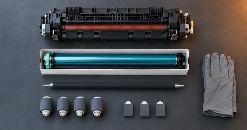
What is in a maintenance kit
Fuser assembly
Bonds toner to the sheet.
Drum unit
Carries the image to the page.
Transfer roller
Moves toner to paper.
Pickup rollers
Feed stock from the tray.
Separation pads
Tension the sheet. Worn pads jam.
Waste toner bottle
Collects what is not transferred.
A maintenance kit is not a service visit in a box. It is a set of specific wear parts, each of which fails in a specific and predictable way.
People treat the maintenance kit as a black box because it arrives as one part number and gets installed in one sitting. That is a reasonable way to handle the purchase order and a poor way to handle troubleshooting. When output starts drifting, knowing which part is nearing the end of its life tells you what to look at first.
A maintenance kit replaces the fuser, the photoconductor drum, the transfer roller, the pickup rollers, and the separation pads. Contents vary per printer, so check the kit for your machine rather than assuming this list is universal. What follows is what each part does, taken roughly in the order a sheet of paper meets them.
The parts that move paper
Pickup rollers take a sheet from the tray and start it down the path. They work by friction, and friction is exactly what wears them. A tired pickup roller does not fail cleanly. It starts by occasionally failing to pick, which reads as a random misfeed, and it ends by failing consistently.
Separation pads sit against the pickup roller and hold back the sheets underneath the one being picked. Their job is to make sure one sheet leaves the tray rather than two. When they wear, you get multifeeds. On an ordinary print job a multifeed is an annoyance. On a check run it is a numbered document that never got printed and a second one buried inside a stack, which is an accountability problem before it is a printing problem.
Neither of these parts touches the image. They affect whether the right number of sheets pass through in the right order, which for check printing is its own category of risk.
It is worth separating those two failures when you describe them to a service technician. A misfeed means the machine did not pick a sheet. A multifeed means it picked more than one. They point at different parts and the words get used interchangeably by people who have not had to order the replacement.
The parts that make the image
The photoconductor drum carries the latent image and picks up toner from it. It is a consumable surface, and as it wears the image it produces degrades. Degradation on a drum tends to show as repeating marks or as a general loss of density, both of which are visible on any page.
The transfer roller moves the toner from the drum onto the paper. This is one of the components that contributes to signal strength on the MICR line. Signal strength is a property of the assembled machine rather than of the toner alone: the engine, the fuser temperature, the transfer roller, and the toner all contribute. A transfer roller that is not moving toner efficiently is taking ink mass off the character, and ink mass is what the read head measures.
The fuser, and why it matters most here
The fuser bonds the toner to the paper. It is the last thing the sheet meets before it reaches the output tray, and it is the part of the kit with the most direct line to MICR performance.
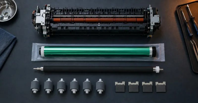
Fuser condition affects toner adhesion, and adhesion affects signal strength. That chain is short and it is worth memorizing, because it explains a failure mode that confuses people: a check that looks correct, printed with the correct toner and the correct fonts, that still reads poorly. If the toner is not properly bonded, some of it does not survive handling, and what survives is what the read head sees.
This is also why fuser temperature appears in any serious discussion of MICR toner formulation. A toner is formulated against the thermal behavior of a particular engine. Change the fuser condition and you have changed one half of that relationship.
Yields are page counts, not calendar intervals
Kit yields are published as page counts. They are not published as time intervals, and there is a reason for that. Every part above wears by use. A roller that picks 200,000 sheets has done the same amount of work whether it did it in one year or in four.
The practical consequence is that the maintenance schedule for a check printing operation has to be driven by a counter, not by a calendar. Two operations that bought the same machine on the same day can be thousands of pages apart within a quarter.
- Record the page counter at every kit installation, so you always know your position within the current kit.
- Order the next kit before the counter reaches the published yield, not after output starts to drift.
- Keep the counter reading next to your reject rate figures, so you can see whether a rise in rejects lines up with a kit nearing its end.
- Treat a kit installation as a change event and verify MICR output afterward, the same way you would after any other change to the machine.
That last point gets skipped often. A maintenance kit replaces several of the components that determine signal strength. The machine after the kit is not quite the machine that was there before it, and it is worth confirming on a MICR verifier that the change moved output in the direction you wanted.
How to think about the kit as a whole
Read the list again and notice how it divides. Two parts move paper. Three parts are involved in getting toner onto the page and keeping it there. For an operation printing ordinary documents, those two groups are roughly equal in importance, because both of them determine whether the output looks right.
For a check printing operation they are not equal. The image group sits directly in the chain that produces signal at a read head, and the paper group does not. When output degrades and the checks still look acceptable, the image group is where the investigation belongs, and the fuser is where it should start.
That is the practical reason to know what is in the box rather than treating the kit as one part number. It is not about installing it yourself. It is about knowing, when somebody asks why the reject rate moved, which of five components you just replaced could plausibly have caused it.
Kit contents and published yields vary by printer. Use the documentation for your specific machine rather than a general figure.